New:
Osmosis Desalination and Carnot
New
Blue Marble the Uniform Earth Image
The Sun and the Moon a Riddle in the Sky
Optimizing the Efficiency of Reverse Osmosis Seawater Desalination
Uri Lachish, guma science
![]()
Abstract: A way is considered to achieve efficient reverse osmosis seawater desalination without use of energy recovery or pressure exchange devices.
Contents
1. Introduction
2. Basic scheme of desalination by reverse osmosis
3. Improving desalination: I. Modules in series
4. Improving desalination: II. Energy recovery
5. Summary of the energy balance
6. A spiral membrane module
7. Cyclic flow operation
8. Desalination energy, salinity and cycle time in cyclic flow operation
9. Comparison of continuous flow to cyclic flow
10. Difficulties with cyclic flow operation
11. Utilization of the energy accumulated within concentrated salt water
12. Summary and conclusions
1. Introduction
Seawater desalination requires minimal energy
consumption equal to the osmotic pressure times the volume of desalinated water [1].
The osmotic pressure is nearly proportional to the salt concentration in the water.
For a seawater osmotic pressure of 27 bar the minimal energy is about 0.75 kW
hour / cubic meter and it varies according to the water salinity.
This minimal energy, derived by thermodynamic
considerations, is general and true to all desalination technologies and not
only reverse osmosis.
Advanced reverse osmosis systems apply energy recovery or pressure conversion devices and report higher energy consumption of above 2 kW hour / m3 [2, 3]. Curiously, the energy may be easily reduced and approach the theoretical minimum. Why this is not done?
Producing one volume of desalinated water with nearly minimal consumption of energy requires the use of several volumes of seawater that mostly go back to the sea. These volumes are prepared prior to desalination by chemical treatment and filtering operations. The cost of the pre osmosis water is then higher than the cost of the energy saved in the process, so there is no advantage doing that.
The ratio of the desalinated water volume to the seawater volume used to produce it is called the recovery ratio. High recovery ratio saves on the cost of seawater preparation prior to the osmosis process, and low recovery ratio saves on the energy cost of desalination. The optimal recovery ratio depends on the relative costs of these operations and may vary under different conditions.
The purpose of these pages is to consider a way to achieve efficient seawater desalination by reverse osmosis in a system that does not apply energy recovery or pressure conversion devices.
2. Basic scheme of desalination by reverse osmosis
Figure-1 shows
the basic scheme of desalination by reverse osmosis:
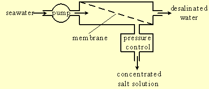
Figure-1: Basic scheme of desalination by reverse osmosis.
High-pressure pump pumps seawater into a module separated by a semi permeable membrane into two volumes. The membrane lets water flow through it but blocks the transport of salts, so the water in the volume beyond the membrane, called permeate, is desalinated, and the salt is left behind in the volume in front of the membrane. The concentrated salt water in this volume leaves the module via a pressure control valve.
The osmotic pressure Ps is given by van't Hoff equation:
Ps = c∙R∙T (1)
Where c is the ionic molar concentration, R = 0.082 (liter bar / degree mole)
is the gas constant, and T is the absolute temperature in Kelvin units. T is
equal to the Celsius temperature + 273.17. Thus, T = 300 K for 27o C.
Typical ionic salt concentration of seawater is: c = 1.1 mole / liter, and the
corresponding osmotic pressure is:
Psea = 1.1 x 0.082 x 300 = 27 bar.
The flow rate of water through the membrane Frate is given by:
Frate = Kf∙(Ppump - Ps) (2)
The membrane properties and its area determine the flow rate factor Kf. Ppump is the pressure generated by the pump and controlled by the pressure control valve. Ps is the osmotic pressure of the concentrated salt water in the module.
The pump pressure must be higher than the osmotic pressure in order to force seawater flow through the membrane and permeate water out of the module. The flow rate is proportional to the difference between the two pressures. When they are equal water does not flow through the membrane, and if the pump pressure is lower than the osmotic pressure, permeate water will flow back towards the concentrated salt water.
Consider an example where the water recovery ratio is 0.5. That is, for every two volumes of seawater pumped into the module one volume will come out as permeate water and one as doubly concentrated salt water. The high-pressure pump consumes energy equal to the pump pressure times the volume of water that it pumps. Since the pump has to pump two V volumes of seawater in order to produce one V volume of permeate water, the consumed work is:
W = P∙2∙V (3)
Since the osmotic pressure of the concentrated salt water is twice as much as that of seawater, Ps = 2∙Psea, the required pump pressure will be:
P = 2∙Psea + ΔP (4)
ΔP is the overpressure, above the osmotic pressure, that drives water flow through the membrane. The work then becomes:W = (4∙Psea + 2∙ΔP)∙V (5)
It is, therefore, more than four times higher than the minimal theoretical desalination energy (Psea∙V).
In summary, the practical desalination energy is higher than the theoretical
minimum for two reasons.
a. The feed volume of seawater is higher than the
volume of permeate-water.
b. The osmotic pressure of concentrated salt water
within desalination module is higher than that of seawater.
3. Improving desalination: I. Modules in series
Figure-2 shows a
desalination system where a number of modules are connected in series. In
practical systems there are six or seven modules in series.
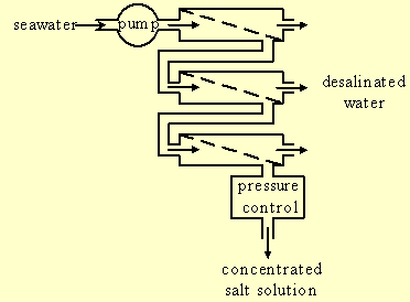
Figure-2: Connecting membrane modules in series.
Seawater flows into a first module where about 10% penetrate through the membrane and become permeate water. The rest more concentrated water flows to a second module where again part of it penetrates through the membrane and part of it continues to the next membrane.
The salt concentration and therefore also the osmotic pressure increase at each consecutive module, while the overall pump pressure is nearly the same in all of them. The flow rate through the membrane is proportional to the difference between the pump pressure and the osmotic pressure (equation 2). Therefore, the pressure difference and the flow rate through the membrane are highest at the first module. They decrease at each consecutive module, and are lowest at the last module.
In this system there is no need of overpressure to drive water through the membranes if sufficient number of modules are connected in series. Most of the permeate-water comes from the first modules and little water comes from the membrane of the last module, where the osmotic pressure is slightly below the pump pressure. For 50% water recovery the work of desalination thus becomes (by equation 5):
W = 4∙Psea ∙V (6)
The semi permeable membrane is not perfect and about 0.5% - 1% of the salt in the water penetrates through it. Series connection of modules is advantageous since most of the water comes from modules with lower salt concentration, resulting in lower salt concentration in the permeate water.
4. Improving desalination: II. Energy recovery
The mechanical
energy consumed by the high-pressure pump is transformed into heat within the
desalination system. Part of the heat is generated by dissipate water flow
through the membrane and part by water flow through the pressure control valve.
Part of the (free) energy is accumulated within the concentrated salt water that leaves
the system. This energy is not lost and in principle can be utilized, returned
back to the system and improve its efficiency. Is it worth doing? The question
will be discussed in a next section.
The energy loss within the pressure control valve can be avoided by application of a variety of energy recovery devices. Figure-3 presents a system where the pressurized salt water, that leaves the membrane modules, drives a rotary turbine [4]. The turbine drives an auxiliary high-pressure pump that supplies seawater to the membrane modules and reduces the water supply and energy consumption of the first pump.
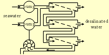
Figure-3: Energy recovery with a turbine and an auxiliary pump.
Water is practically incompressible and therefore cannot accumulate energy. This property is the basis of a class of devices that exchange pressurized concentrated salt water within the modules with outside seawater [5 - 12]. There are many specific designs but they all operate with the same "rotating door" principle presented in figure-4.
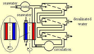
Figure-4: Exchange of pressurized concentrated salt water with seawater.
The "rotating door" has two compartments, one filled with pressurized concentrated salt water, and one filled with seawater. The "door" rotates 180 degrees and exchanges the positions of the two compartments (as seen on the left of figure-4). By that it introduces seawater to the high-pressure line of the modules and relieves pressurized concentrated salt water to the seawater line. The seawater in the right compartment now flows towards the membranes and is replaced by another dose of concentrated salt water. The concentrated salt-water in the left compartment flows away and is replaced by fresh seawater. The "door" then rotates 180 degrees again. The operation involves pressurizing seawater and depressurizing concentrated salt water. Since water is incompressible, these processes do not involve consumption or waste of energy.
Many practical systems do not look like figure-4 at all, but rather apply mechanisms of moving pistons and valves to achieve this mode of a "rotating door" operation [5 - 11]. One company has developed a continuously rotating high-speed rotor for this purpose [3, 12].
In the limit of a 100% efficient energy recovery device, the externally powered pump will supply a volume V of seawater equal to the volume V of the delivered permeate water. The rest of the required seawater comes from the energy recovery device. The work of desalination, P∙V, is far lower than in systems that do not apply energy recovery because now V is the volume of permeate water and not of seawater supply. For the case of 50% water recovery the pressure is P = Ps = 2∙Psea and the desalination work is:
W = Ps∙V = 2∙Psea∙V (7)
It is half of the work required by a system without energy recovery, calculated in equation 6. In practical systems an energy recovery efficiency of 70 - 80% is reported for turbine type devices, and over 90% for rotating door type devices. The work of desalination is then higher than the ideal value of equation 7.
The osmotic pressure at the system exit for any water recovery ratio α(α = output volume of permeate water / input volume of seawater) is Ps = Psea / (1 - α), and the corresponding work of desalination is:
W =Psea∙V / (1 - α) (8)
The calculation for energy recovery efficiency below 100% is given in the appedix. Figure-5 shows the minimal desalination energy as a function of the water recovery ratio for the energy recovery efficiencies 0, 0.85, 0.9, 0.95, and 1.
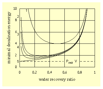
Figure-5: Dependence of the minimal desalination energy on the water recovery ratio for the energy recovery efficiencies
0 (1), 0.85 (2), 0.9 (3), 0.95 (4), and 1 (5).
One energy unit in the figure is the theoretical limit Psea∙V, equal to 0.75 kWatt Hour / cubic meter for osmotic pressure of 27 bar. The work of desalination decreases and approaches the theoretical limit as α is reduced. The optimal α value is determined by the energy cost compared to the cost of pre-osmosis water, as discussed in the introduction.
5. Summary of the energy balance
The work consumed by the pump is equal to P∙V where P is the pump pressure and V is the
volume of seawater that it pumps. All this work is transformed into heat.
Ps is the osmotic pressure of the concentrated salt solution within a membrane module and ΔP is the over pressure that drives water flow through the membrane. The pump pressure P is equal to their sum, P = Ps + ΔP. When modules are connected in series Ps and ΔP change from module to module but their sum is nearly the same. Ps is lowest at the first module and it increases with each successive module.
Vpermeate is the volume of desalinated water produced by the process and Vconcentrate is the volume of concentrated salt solution that returns to the sea. In systems that do not apply energy recovery devices the overall pumped volume is equal to the sum V = Vpermeate + Vconcentrate. In systems that apply energy recovery devices of 100% efficiency the volume pumped by the pump is equal to the volume of desalinated water, V = Vpermeate.
Table 1 summarizes the energy losses, how they can be reduced, and for what price.
|
Loss |
Type |
Reduce by |
The price |
|
Ps∙Vpermeate |
Thermodynamic transformation of mechanical energy into heat. |
Decrease the osmotic pressure Ps by reducing the water recovery ratio. |
Higher consumption of seawater. |
|
ΔP ∙Vpermeate |
Dissipate heat of water flow through the membrane |
Lower water throughput. |
Lower utilization of the desalination plant |
|
P∙Vconcentrate |
Dissipate heat of water flow through the pressure control valve. |
Application of energy recovery or pressure exchange devices. |
More equipment |
Note:
W = P∙V
Where W is the pump work, P is the pump pressure, and V is the volume of pumped
water.
W = P∙V ∙ 100
for W in Joules (Watt seconds), P in bars, and V in Liters.
Or,
W = P∙V / 36
for W in kWatt hours, P in bars, and V in cubic meters.
For example, the energy required to pump a volume of V = 1 cubic meter of salt water with osmotic pressure of
Ps = 27 bar, through a semi permeable membrane , is:
W = 27 ∙ 1 / 36 = 0.75 kWatt hour.
6. A spiral membrane module
Figure-6 shows the water flow within a
spiral membrane module
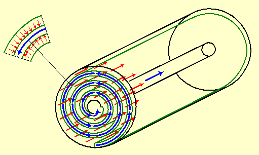
Figure-6: Spiral membrane module.
The membrane is shaped into a spirally wound flat sleeve (green) contained in a high-pressure cylinder. The sleeve is closed at the spiral sides and outer end, and the inner end is connected to a central pipe. Pressurized seawater (red arrows) flows in the direction of the cylinder axis along the external surface of the membrane sleeve. Some water penetrates through the membrane and leaves the salt behind, thus it turns into permeate water within the sleeve. Permeate water (blue arrows) flows within the spiral sleeve towards the central pipe that leads it out of the module.
Water that penetrates through the membrane leaves behind it a locally highly concentrated salt at the external surface of the membrane. This concentrated salt immediately stops any further water flow through the membrane unless it is removed fast enough by a lateral seawater flow along the surface.
The membrane sleeve is supported from its inside with a porous spacer that prevents sleeve collapse by the osmotic pressure. Another porous spacer surrounds the sleeve and stabilizes the space of seawater flow.
The module manufacturer supplies the testing conditions of the membrane module. For example, the following data is given for "FILMTEC 8" Seawater RO Elements" (SW30HR-380) by "DOW" [13].
Module size: Length 1016 mm, diameter 201 mm, diameter of central pipe 29 mm.
Operating pressure: 55.2 bar (800 psi), (max 70 bar (1015 psi).
Max Feed
Flow: 14 m3 / hour.
Product water flow rate: 23 m3 /
day at 25o C.
Single element recovery (Permeate Flow to Feed
Flow): 0.08 (max 0.15 at lower feed flow).
Salt (NaCl) concentration: 32000
ppm (32 gram / liter).
These numbers give:
Feed water flow of 200 (max 233) liter / minute.
Permeate water flow of 16 liter / minute.
Osmotic pressure of 27 bar
(390 psi), calculated by van't Hoff formula (equation 1).
Flow rate factor
(equation 2):
Kf = Frate / (P - Ps) = 16 / (55.2 - 27) = 0.57 (liter / minute) / bar (9)
7. Cyclic flow operation
Sections 2 - 6 describe the reverse
osmosis technology of seawater desalination. The rest of these pages are
theoretical considerations and calculations by the author.
Semi permeable membranes favor operation with continuous water flow and permanent operating pressure. Flow disturbances and unstable pressure stress the membranes and increase their wear. However, the continuous flow mode requires application of energy recovery devices for efficient operation.
An operation mode of cyclic flow may achieve, in principle, energy efficiency comparable to continuous flow and there is no need of energy recovery devices. Therefore, this possibility may not be ignored, even for a price of modifying the semi permeable membrane or the membrane module.
The system described in figure-7 includes a low pressure circulating pump and a two-state valve.
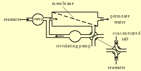
Figure-7: Seawater desalination in a cyclic water flow.
At one state of the valve the salt-water compartment of the module is closed. The high-pressure pump pumps seawater into the membrane module and all the water penetrates through the membrane and turns into permeate water since there is no other water exit. The low-pressure pump circulates the water in the module at a flow rate required by the module manufacturer for proper operation. Since there is no exit for the salt it will accumulate within the module and steadily increase the osmotic pressure. At a pre determined osmotic pressure the valve revolves and relieves the pressure within the module.
At this state of the valve the two pumps drive the concentrated salt water out of the module and replace it with fresh seawater. The valve then revolves again and the operation is repeated.
Pressure release of concentrated salt water by valve revolution does not waste energy, similarly to the case of the "rotating door" (section 4), since water is incompressible and does not accumulate energy. However, there are other energy-losses that will be considered later.
In cyclic operation the high-pressure pump pumps a volume of seawater equal to the volume of delivered permeate water. In this respect it is equivalent to continuous operation with an energy recovery device. Only here there is no such a device. Efficient continuous operation without energy recovery is achieved with deep sea deslination by reverse osmosis [14 - 15].
8. Desalination energy, salinity and cycle time in cyclic flow operation
Since the pressure increases with the salt concentration of
salt-water within the module, the work of pumping water through the membrane
will be:
W = ∫p∙dV = ∫(Ps + ΔP) ∙dV (10)
where Ps is the increasing osmotic pressure. The over pressure ΔP is determined by the flow rate of the high-pressure pump ΔP = Frate / Kf.
The salt concentration cs within the module is given by:
cs = csea∙ (V + V0) / V0 (11)
where csea is the salt concentration of seawater, V0 is the salt-water volume within the module, and V is the delivered permeate water. Since the osmotic pressure is proportional to the salt concentration it is given by a similar equation:
Ps = Psea∙(V + V0) / V0 (12)
The work of desalinating a volume V of permeate water will be (by inserting equation 12 into equation 10 and integration):
W = Psea∙(0.5∙V2 / V0 + V) + ΔP∙V (13)
Or:
W = (Psea∙(0.5∙V / V0 + 1) + ΔP)∙V (14)
Or:
W = (Psea∙(1 - α / 2) / (1 - α) + ΔP)∙V (15)
Where α = V' / (V' + V0) is the recovery ratio. V' is the volume of permeate water delivered in one cycle.
In cyclic operation there is no need to connect modules in series. This is an advantage that leads to higher permeate water throughput.
Salinity, the salt concentration in permeate-water for 1% salt penetration through a semi permeable membrane, is:
Salinity = 0.01∙ [∫cs∙dV] / V (16)
where cs is the salt concentration of salt water within the module
and V is the volume of permeate water.
cs =(csea /
Psea)∙Ps by using equations (10) - (12), therefore:
Salinity = 0.01∙ (csea / Psea)∙ [∫Ps∙dV] / V = 0.01∙ csea ∙ (1 - α / 2) / (1 - α) (17)
The cycle time in cyclic operation depends on the seawater volume within the module. Using the module dimensions in section 6 its internal volume is estimated to be 32 liter. Assuming that half of this volume is solid material, membrane and spacers, and the rest is divided to equal volumes of salt-water and permeate-water, the salt-water volume will be V0 = 8 liter. This is a coarse estimate.
The permeate-water recovery ratio is α = V' / (V' +
V0) , where V' is the permeate-water delivered per cycle.
V' = Frate ∙ t, where Frate is the permeate-water flow rate and
t is the cycle time. Therefore, the cycle time in seconds is:
t = 60 ∙ (V0 / Frate) ∙ α / (1 - α) (18)
Calculated values of the desalination energy, salinity, cycle time and water throughput are given in the next section.
The cycle time may be increased by connecting an auxiliary tank in series to the salt water side of the membrane module. It is also possible to alternately connect two tanks so that in one tank pressurized water circulates with increasing salt content while the other tank is flushed with seawater and vice versa. In this case the membrane module may be loaded under permanent pressure. Such a system, however, requires the operation of more valves.
9. Comparison of continuous flow to cyclic flow
The comparison is done for the testing parameter values mentioned in section 6. Higher values may
be applied to practical operation, though they should not exceed the operating
limits.
a. Continuous flow system equipped with 6 modules connected in series, and
with a 100% efficient energy recovery device.
Table 2 summarizes the
operation parameters.
|
Feed Flow |
Permeate Flow (liter / min) |
|||||||
|
Pressure |
Feed (L/min) |
1st Module |
Water Recovery |
Energy |
Salt |
|||
|
bar |
Pump |
Recovery |
% |
V1 |
α (%) |
V |
kWh/m3 |
mg/L |
|
55.2 |
78 |
155 |
7 |
16 |
33.5 |
78 |
1.53 |
377 |
|
55.2 |
74 |
136 |
8 |
16 |
37 |
74 |
1.53 |
385 |
|
55.2 |
50 |
50 |
16 |
16 |
50 |
50 |
1.53 |
414 |
|
45.4 |
50 |
150 |
5.2 |
10.5 |
25 |
50 |
1.26 |
360 |
The table is calculated by the equations:
Ps(1) = Psea (19)
Permeate(i) = Kf ∙ (Ppump - Ps(i)) (20)
Supply(i) = Σ(j = 1 to i) Permeate(j) (21)
Ps(i + 1) = Psea ∙ Feed / (Feed - Supply(i)) (22)
W = Ppump∙V (23)
Salinity = 0.01 ∙ csea ∙ (Σ Permeate(i) ∙ Ps(i) / Psea) / Supply(6) (24)
Ps(i) is the osmotic pressure in the i'th module.
Permeate(i)
is the permeate water flow of the i'th module.
Supply(i) is the sum of
permeate water flows of the first i modules.
Psea = 27 bar is the
osmotic pressure of seawater at 300 K (27o C).
csea =
32 gram / liter is the salinity of seawater.
Ppump is the pump
pressure in bars, given in the table.
Kf = 0.57 (liter / minute) / bar is
the flow rate factor.
α is the permeate-water
recovery ratio.
V is the volume of delivered permeate-water.
V1 is the volume of permeate-water delivered by the first module.
Feed, given in the table, is the water feed flow through a module. Feed is
the same for all modules since they are connected in series.
The work of desalination per 1 m3 of permeate-water is:
W/V = Ppump∙100 (Joule / liter = Watt second / liter) = Ppump∙100 / 3600 (kW hour / m3) (25)
Salinity, the amount of salt in permeate-water is calculated for %1 salt penetration through semi permeable membrane.
Notes:
I. The calculation is somewhat
inaccurate since it assumes uniform salt concentration within each module while
the concentration does change within each one.
II
. The desalination energy calculated in the table assumes 100% energy recovery. In practical systems, with lower energy recovery, the desalination energy will be higher than the table values, and the difference will increase as the water recovery ratio decreases.III
. Comparison of lines 1 - 3 demonstrates the effect of increasing the water recovery ratio by reducing the overall feed rate of seawater. Higher ratio saves pre-osmosis seawater but reduces the throughput of permeate-water.IV
. Comparison of lines 2 - 4 demonstrates the effect of pump pressure on the system performance. Higher pressure saves pre-osmosis seawater and increases the throughput of permeate-water, but also increases the energy of desalination.b. Cyclic flow system equipped with 6 modules connected in parallel.
In a cyclic system there is no need to connect modules in series. The
modules are connected in parallel and the flow in each module is 1 / 6 of the
overall flow.
Table 3 summarizes the operation parameters for permeate water supply similar to table 2.
|
Feed Flow |
Permeate Flow (liter / min) |
||||||||||
|
Pressure (bar) |
Feed (L/min) |
1 module |
Recovery |
Energy |
Salt |
cycle |
|||||
|
ΔP |
Pstart |
Pend |
Pump |
Flush |
% |
V1 |
α( ) |
V |
kWh/m3 |
mg/L |
sec |
|
22.8 |
49.8 |
63.4 |
78 |
155 |
5.6 |
12.8 |
33.5 |
78 |
1.57 |
401 |
20.5 |
|
21.6 |
48.6 |
64.5 |
74 |
136 |
6.2 |
12.3 |
37 |
74 |
1.57 |
414 |
25.1 |
|
14.6 |
41.6 |
68.6 |
50 |
50 |
8.3 |
8.3 |
50 |
50 |
1.53 |
480 |
63.4 |
|
14.6 |
41.6 |
50.6 |
50 |
150 |
4.2 |
8.3 |
25 |
50 |
1.28 |
373 |
21.1 |
|
28.2 |
55.2 |
70 |
96 |
173 |
8.3 |
16 |
35.7 |
96 |
1.74 |
409 |
16.6 |
The table is calculated for the pumping period only. The period required to flush the concentrated salt water in the module and replace it with fresh seawater is about 10% of the pumping period. Therefore, the overall cycle is about 10% longer than the table values, and the flow rates per overall cycle are about 10% lower than the table values.
The Feed and Water Recovery columns are identical to table 2 (except the last line), so that the two processes are compared for the same permeate-water recovery-ratio and throughput.
The table is calculated by the equations:
ΔP = (V / 6) / Kf (26)
Pstart =Psea + ΔP (27)
Pend = Ps +ΔP = P sea / (1 - α) + ΔP (28)
W / V = (Psea∙ (1 - α / 2) / (1 - α) + ΔP) / 36 (29)
ΔP is the over pressure that drives water flow
through the membrane.
V is the delivered volume of permeate-water.
V1 is the volume of permeate-water delivered by one module.
Kf = 0.57 (liter / minute) / bar is the flow rate factor.
Pstart is the pressure at the start of the pumping cycle.
Psea = 27 bar is the osmotic pressure of seawater.
Pend is the pressure at the end of the pumping
cycle.
α = V' / (V' + V0) is the permeate-water recovery
ratio.
V' is the volume of permeate water delivered in one cycle.
V0 = 8 liter is the volume of salt water within a module.
W /
V is the desalination energy per 1 m3 of permeate-water (equation 15,
section 8).
The permeate water salinity is calculated by equation 17,
section 8.
csea = 32 gram / liter is the salt concentration of
seawater.
c. Conclusion
Comparison of the two tables indicates that the
energy of desalination in the two processes, operated at similar permeate-water
recovery ratios and throughputs, is practically the same. However, the two
processes have further energy losses not considered in the tables.
In the continuous flow process there is a full permeate-water flow only at the first module and the flow drops at each successive module. Therefore the capacity of permeate-water flow is not fully utilized. Compared to that, in the equivalent cyclic process the modules are connected in parallel and the permeate-water flow per module is lower than the permitted limit value. Alternatively (line 5 of table 3), the cyclic process can operate at the highest permitted permeate-water flow and achieve higher permeate-water throughput per module, though, at a cost of a higher desalination energy.
10. Difficulties with cyclic flow operation
Apart from variable pressure operation that might wear or even damage the
membrane, other factors should be considered as well. Any part of the system
that accumulates energy will waste it in the cyclic process.
Consider a possible expansion of the high-pressure cylinder that contains the
membrane unit by the pressurized water in it. If the 201 mm diameter cylinder
expands by one millimeter its inner volume will increase by V = 0.4 liter. The
energy accumulated in the cylinder is equal to p∙ V / 2 and it is lost when the
pressure is relieved. Inserting
p = Psea = 27 bar, and V = 0.4 ∙
10-3 m3, the energy will be E = (27 / 36) ∙ 0.4 ∙
10-3 / 2 = 0.15 ∙ 10-3 kW hour per cycle. If a cycle
delivers about 8 liters of permeate-water, the energy loss will be 0.15 ∙
10-3 ∙ 1000 / 8 = 0.02 kW hour per one m3 of permeate
water.
Similar loss might come from pressure squeezing of the permeate-water spacer within the membrane sleeve, and the loss can be calculated in a similar way. A more rigid spacer material, and possibly, mechanically pre squeezing the membrane unit within the cylinder, may reduce the loss.
When a number of modules are connected in parallel to one pump it is important to have similar water flow in each of them to within tight tolerance. Otherwise, in some modules the replacement of concentrated salt water with seawater will not be complete, while in other modules there will be excessive flow and loss of seawater.
The concentrated salt water within the membrane module is replaced by fresh seawater when the pressure is relieved. During this time permeate water will start to flow back through the membrane towards the salt-water. According to specs, the flow rate of salt-water, in parallel to the membrane, is at least ten times higher than the flow rate of permeate-water through the membrane. Therefore, the time of seawater replacement will be about ten times shorter than the time of permeate-water pumping, and the permeate water loss will be less than 10%. The back flow of permeate-water is not completely negative since it automatically flushes the membrane during each cycle.
11. Utilization of the energy accumulated within concentrated salt water
Figure-8 presents a scheme for utilizing energy from concentrated salt water.
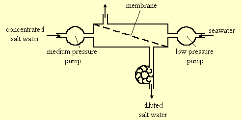
Figure-8: Utilizing energy from concentrated salt water.
A low-pressure pump flushes one compartment of a membrane module with seawater, while a medium-pressure pump pumps concentrated salt water via the other compartment. The pressurized water drives a turbine that supplies mechanical energy. The pressure difference that drives water through the membrane is:
ΔP = Ppump + Psea - Ps
(30)where Ppump is the pump pressure, Psea is the osmotic pressure of seawater and Ps is the osmotic pressure of the concentrated salt water. If the pressure difference is negative, ΔP < 0, or, Ppump < Ps - Psea, water will flow from the seawater side of the membrane towards the concentrated water side. The volume of water that drives the turbine is then equal to the sum of a volume V delivered by the pump, and a volume V1 that flows through the membrane. The work consumed by the pump is Ppump∙ V and the work that drives the turbine is Ppump∙ (V + V1). Therefore there is a net energy profit of Ppump∙ (V + V1) - Ppump∙ V = Ppump∙ V1 that comes from dilution of the concentrated salt water.
The size of a membrane module for utilizing concentrated salt water is similar to that of a desalination module, and, as seen in figure-8, it has four different water outlets instead of three. Therefore, addition of salt utilizing ability to a desalination plant practically means using two different types of membrane modules and doubling their number. In addition to that the energy utilizing process consumes more seawater.
Apart from investing in more membrane modules of a type that doesn't exist yet, the consumption of extra seawater makes energy utilization of concentrated salt water a non-beneficial process. The same amount of extra seawater may alternatively be added to a standard desalination system and save more energy by the reduction of the water recovery ratio. The use of more seawater in a desalination system reduces the osmotic pressure within it, and the reduced pressure saves energy consumption in systems equipped with an energy recovery device, as discussed in section 4.
In summary of this section, there is no benefit in utilizing the (free) energy accumulated within the concentrated salt water. The same amount of seawater, required to dilute the concentrated salt, will achieve higher energy saving by adding it into a standard desalination system, without the need to invest in extra equipment.
12. Summary and conclusions
A cyclic operated system that does not
apply energy recovery devices is suggested for seawater desalination by reverse
osmosis. The desalination energy, product water salinity and system throughput
are comparable to that of continuous water flow systems that do apply energy
recovery devices.
Appendix: Energy recovery efficiency below 100%
Consider a system operating with a water recovery ratio α and with an energy recovery
device of efficiency Ef.
V = α ∙ Vsea is a volume of permeate water
and Vsea is the overall volume of seawater used to produce it. Out of the volume Vsea, a
volume V is delivered by the pump, and the rest of the seawater volume
Vsea - V = V∙ (1 / α - 1) is delivered by the energy recovery device.
The work done by the pump is P ∙ V where P is the pump pressure. For the volume V ∙ (1 / α - 1) delivered by the energy recovery device there is a need to add an energy (1 - Ef) ∙ P ∙ V ∙ (1 / α - 1) to compensate for the incomplete efficiency. Adding together the work of the pump and the energy added to the recovery device yields:
W = P ∙ V ∙ [1 + (1 - Ef) ∙ (1 / α - 1)] (31)
For example, the work for efficiency Ef = 0.95 and water recovery ratio α = 0.1 is
W = P ∙ V ∙ [1 + 0.05 ∙ 9] = P ∙ V ∙ 1.45, compared to P ∙ V, for the efficiency Ef = 1. Therefore, for a recovery ratio of 0.1, a system
with 95% efficient energy recovery device consumes 45% more energy than a system without any recovery loss.
The minimal desalination energy for recovery without loss is given by equation 8, P ∙ V = Psea ∙ V / (1 - α). Therefore the minimal desalination energy for a system including the energy recovery loss will be:
Wmin = Psea ∙ V ∙ [1 + (1 - Ef) ∙ (1 / α - 1)] / (1 - α) (32)
See:
Osmosis Reverse Osmosis and Osmotic Pressure what they are
Desalination machine
Energy of Seawater Desalination
A Pipe of Fresh Water instead of "Canal of the Seas"
references
- "Energy of Seawater Desalination", https://urila.tripod.com/desalination.htm, April (2000).
- P. Geisler, W. Krumm , and T.A. Peters, Reduction of the energy demand for seawater RO with the pressure exchange system PES, Desalination 135 (2001) 205-210. http://www.desline.com/articoli/4050.pdf
- J.P. MacHarg, The Real Net Energy Transfer Efficiency of an SWRO Energy Recovery Device. http://www.energy-recovery.com/tech/real.pdf
- R.A. Oklejas, Apparatus for improving efficiency of a reverse osmosis system, US patent no 6139740 (2000).
- R. Verde, Equipment for desalination of water by reverse osmosis with energy recovery US patent application no 2001/0017278 (2001).
- P. Elliot-Moore, Energy recovery device, US patent application no 2001/0004442 (2001).
- C. Pearson, Fluid driven pumps and apparatus employing such pumps, US patent no 6203696 (2001).
- W.D. Childs, A. Dabiri, Integrated pumping and/or energy recovery system, US patent no 6017200 (2000).
- R.J. Raether, Apparatus for desalinating salt water, US patent no 5916441 (1999).
- S. Shumway, Linear spool valve device for work exchanger system, US patent no 5797429 (1998).
- G.B. Andeen, Fluid motor-pumping apparatus and method for energy recovery, US patent no 4637783 (1987).
- L.J. Hauge, Pressure exchanger having a rotor with automatic axial alignment, US patent no 5988993 (1999).
-
DOW, FILMTEC SW30HR-380 Membrane Elements.
Membrane System Design Guidelines. - D.C. Bullock, and W.T. Andrews, Deep Sea Reverse Osmosis: The Final Quantum Jump. http://www.desalco.ky/d-pdfs/deepsea.pdf
- P. Paccenti, M. de Gerloni, M. Reali, D. Chiaramonti, S.O. Gartner, P. Helm, and M. Stohr, Submarine seawater reverse osmosis desalination system, Desalination 126 (1999) 213 - 218. http://www.desline.com/articoli/3797.pdf
On the net: May, revised September 2002, Appendix added January, references added March 2003.
By the author:
- "Osmosis Desalination and Carnot", https://urila.tripod.com/Osmosis_Carnot.htm, December 2012.
- "Light Scattering", https://urila.tripod.com/scatter.htm, August (2011).
- "The Sun and the Moon a Riddle in the Sky", https://urila.tripod.com/moon.htm, July (2011).
- "Osmosis and thermodynamics", American Journal of Physics, Vol 75 (11), pp. 997-998, November (2007).
- "van't Hoff's Evidence", https://urila.tripod.com/evidence.htm, October (2007).
- "Osmosis and Thermodynamics", https://urila.tripod.com/osmotic.htm, January (2007).
- "Expansion of an ideal gas", https://urila.tripod.com/expand.htm, December (2002).
- "Optimizing the Efficiency of Reverse Osmosis Seawater Desalination", https://urila.tripod.com/Seawater.htm, May (2002).
- "Boltzmann Transport Equation", https://urila.tripod.com/Boltzmann.htm, May (2002).
- "Energy of Seawater Desalination", https://urila.tripod.com/desalination.htm, April (2000).
- "Avogadro's number atomic and molecular weight", https://urila.tripod.com/mole.htm, April (2000).
- "Vapor Pressure, Boiling and Freezing Temperatures of a Solution", https://urila.tripod.com/colligative.htm, December (1998).
- "Osmosis Reverse Osmosis and Osmotic Pressure what they are", https://urila.tripod.com/index.htm, February (1998).
- "Calculation of linear coefficients in irreversible processes by kinetic arguments", American Journal of Physics, Vol 46 (11), pp. 1163-1164, November (1978).
- "Derivation of some basic properties of ideal gases and solutions from processes of elastic collisions", Journal of Chemical Education, Vol 55 (6), pp. 369-371, June (1978).
Links:
- Thermodynamics Research Laboratory, http://www.uic.edu/~mansoori/Thermodynamics.Educational.Sites_html
- Thermodynamik - Warmelehre, http://www.schulphysik.de/thermodyn.html
- The Blind Men and the Elephant
- My Spin on Lunacy
- Five Weeks in a Balloon
- The first man I saw
- "Faster, Faster!"
- Perfection can't be rushed
- The man higher up
- Brains
- The First-Class Passenger
- other